


This is the second part of our 2-parts introduction series on the Waylay rules engine. You can read the first part here and find out more about rule patterns on our technical documentation site.
In this article, we primarily cover the default capabilities of the engine. If interested in the advanced expert mode, you can find more information in our granted patent US20160125304. The expert mode engine is available to enterprise customers.
The Rational Agent
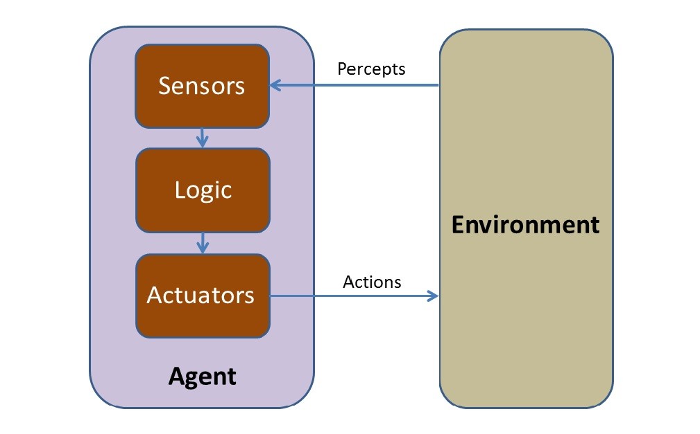
The rational agent is a central concept in artificial intelligence. An agent is something that perceives its environment through sensors and acts upon that environment via actuators. For example, a robot may rely on cameras as sensors and act on its environment via motors.
The Bayesian Network
A Bayesian network is a probabilistic directed acyclic graphical model that represents a set of random variables and their conditional dependencies via a directed acyclic graph.
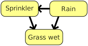
One simple example of a Bayesian network: rain influences whether the sprinkler is activated, and both rain and the sprinkler influence whether the grass is wet. (example taken from wikipedia)
Conditional probability table (CPT)
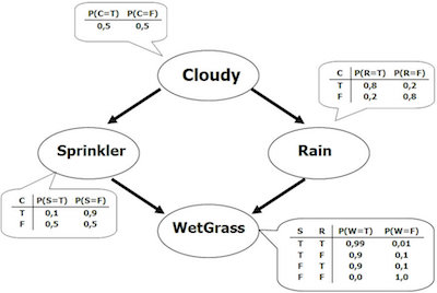
In statistics, the conditional probability table (CPT) is defined for a set of discrete (not independent) random variables to demonstrate marginal probability of a single variable with respect to the others. For our previous example, CPT table might look like this:

Using the CPT table, one can answer questions such as: “What is the probability that it is raining, given that the grass is wet?” or “What is the probability of the sprinkler being turned on given that the grass is wet?” or “What is the probability of the grass being wet giving that it is raining?” and so on.
One might even go even further and introduce cloudy weather or humidity as variables into the same problem, like in the example below:
Waylay abstractions on top of the bayesian network
In our default SaaS offering, the Waylay designer models only the independent random variables – which we call sensors, while the conditional dependencies are modelled using CPT (so in the picture above, the relation sprinkler<-rain would not be possible). Also, in our SaaS offering, the conditional dependencies are expressed using “simplified” CPT tables (where we only create zeros and ones in the table), which we call gates.
Actuations are simple functional calls (fire and forget) associated with outcomes (observations) of either sensors or gates – which must be completely observed (posterior probability is 1) – meaning that the sensor has returned the state or gate is in one of the states with posterior probability 1.
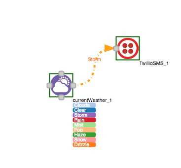
For instance the rule you see below: send SMS (actuation) in case that the weather condition (sensor) is storm (state), would be modelled with only one sensor, without gates, where the actuator is attached to the weather sensor.
Waylay Sensors and Actuators
In Waylay, the random variable (node) is a sensor that encapsulates a particular random variable that can be observed via the attached sensor function. For every node, there are three groups of settings:
- Settings that control when the sensor will be executed: by polling, execute on data stream using the resource concept, execute on the task tick (polling/cron…), sequence number, state change from another sensor triggering the execution etc.
- Settings that control how long the sensor information is valid: eviction by time or by resetObservation flag – which would simply reset the observed node just before the sensor function executes
- Input parameters that are used by sensor functions: such as city, device id etc.
You can find more information on task/node parameters here.
The sensor function is a stateless call that returns back either a state or raw data or both. Here is one example of the JSON result:
In case that the sensor is not observed, or if the node is reset by the task (what we call a resetObservation) the sensor states will go back to priors. In our SaaS offering, that means that the priors will be the same for all states, with the total sum of all priors being 1 (e.g. if node has two states, the prior will be 0.5 for each state).
The actuator function is a simple fire and forget call that either triggers on a given state, a set of states, or the state change of the node to which the actuator is attached.
You can find more information on sensors and actuators here.
Building logical statements using CPT table
Let’s consider these two sentences:
- I am very happy when I eat chocolate AND when I watch football.
- I am very happy when I eat chocolate OR when I watch football.
From this simple example, we see how often we use AND in a sentence to actually express an OR relation.
In Waylay, we have come up with simple abstractions for CPT, which we call gates, and we define three types of CPT tables:
- AND
- OR
- GENERAL
The first two gates (AND, OR) somewhat resemble Boolean Logic, although there are some important differences:
- The first difference is that all gates can be attached to a “non binary” sensor (a sensor having more than two states),
- The second major difference is that you should not assume that both sensors need to be observed in order to have the gate state with posterior probability 1 (in case of AND gate that would be FALSE state, while for OR gate that would be TRUE state, see later).
That second difference is very important if we attach an actuator or sensor to the gate, as they both expect the gate to be completely observed (1) before actuation or before triggering another sensor which is attached to that gate.
In case of doubt, our suggestion is to always start with a GENERAL gate in case you need an either relation, meaning “either this state of nodeX or that state of nodeY”.
GENERAL gate
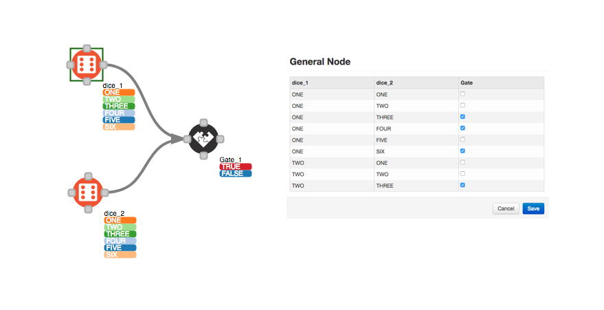
Let’s assume we roll a dice and want to have a TRUE state of the Gate_1 when either dice_1 is in state ONE OR dice_2 is in state THREE. The GENERAL gate settings will look like this:
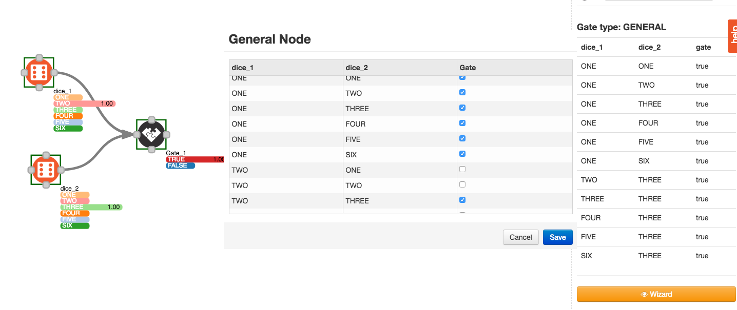
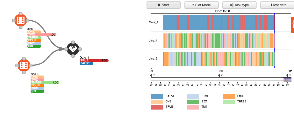
At runtime, you should see something like this:
AND gate
Here is an example of an AND gate for two nodes with only two states, where we model the only condition that leads to a TRUE state.
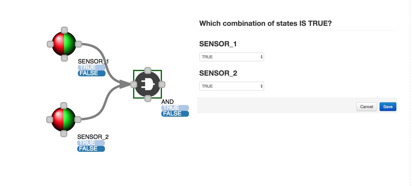
And here is its corresponding CPT table:
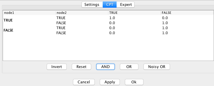
If we look at the CPT table above, we can see that as soon as one of the nodes is in the state FALSE, the gate will be in the state FALSE. On the other hand, both nodes must be observed to state TRUE, to have the AND gate in state TRUE as well.
The same gate can be applied to more than 2 nodes, and more than 2 states per node.
(N)OR gate
Here is an example of an OR gate for the same nodes, where we model only the condition that leads to a FALSE state.
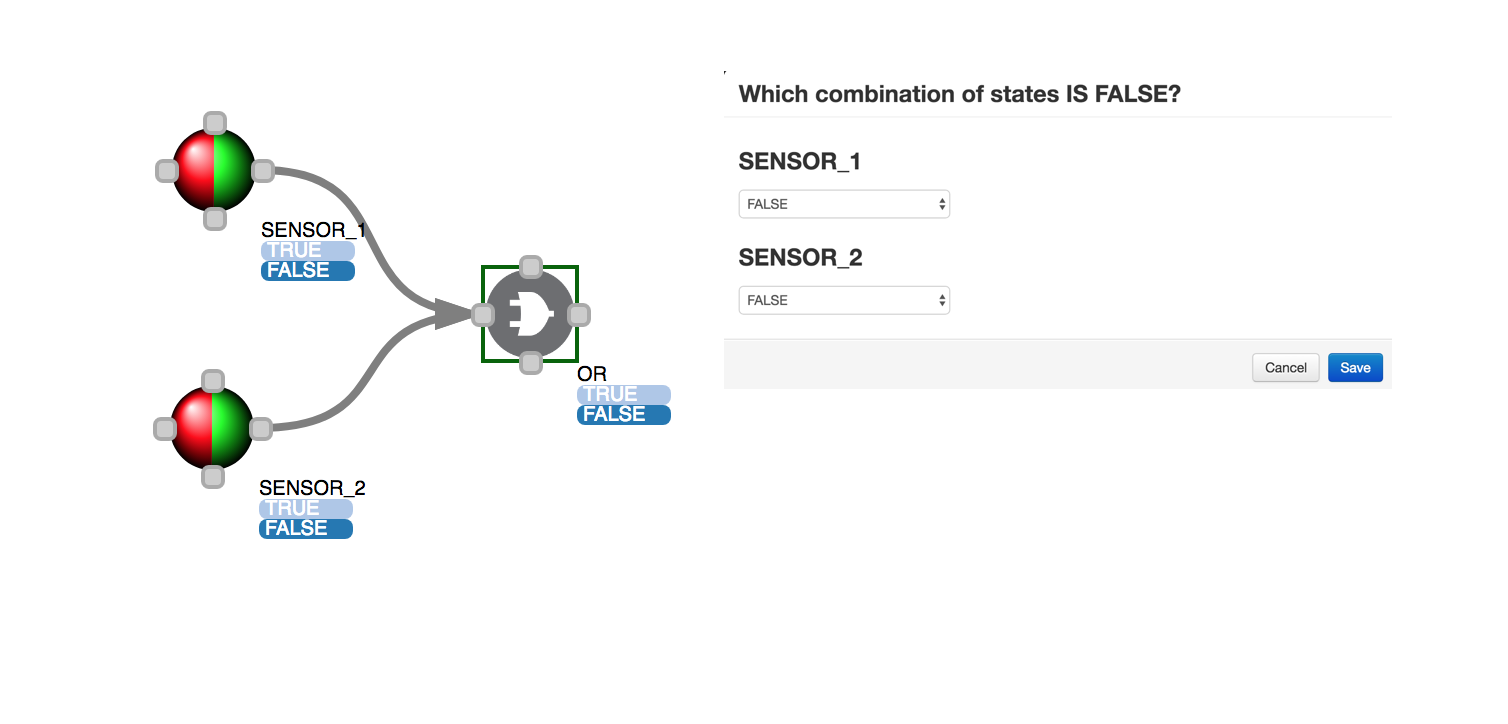
and here is its corresponding CPT table:
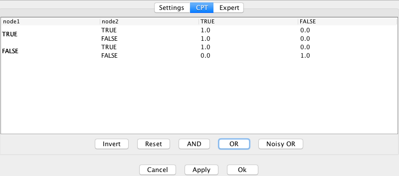
This table tells that only if both nodes return state TRUE the gate will be in the state TRUE. Again, we can apply the same gate for multiple nodes and with more than 2 states, but the CPT table will always look the same, with only one combination leading to FALSE state.
The reason why some people consider this as a NOR gate is because in boolean logic, NOR is a gate that for two binary inputs produces TRUE state only when both inputs are FALSE. In our case, we can model any state combinations which lead to a single FALSE state of the gate, so in that sense, we are trying not to confuse users even more.
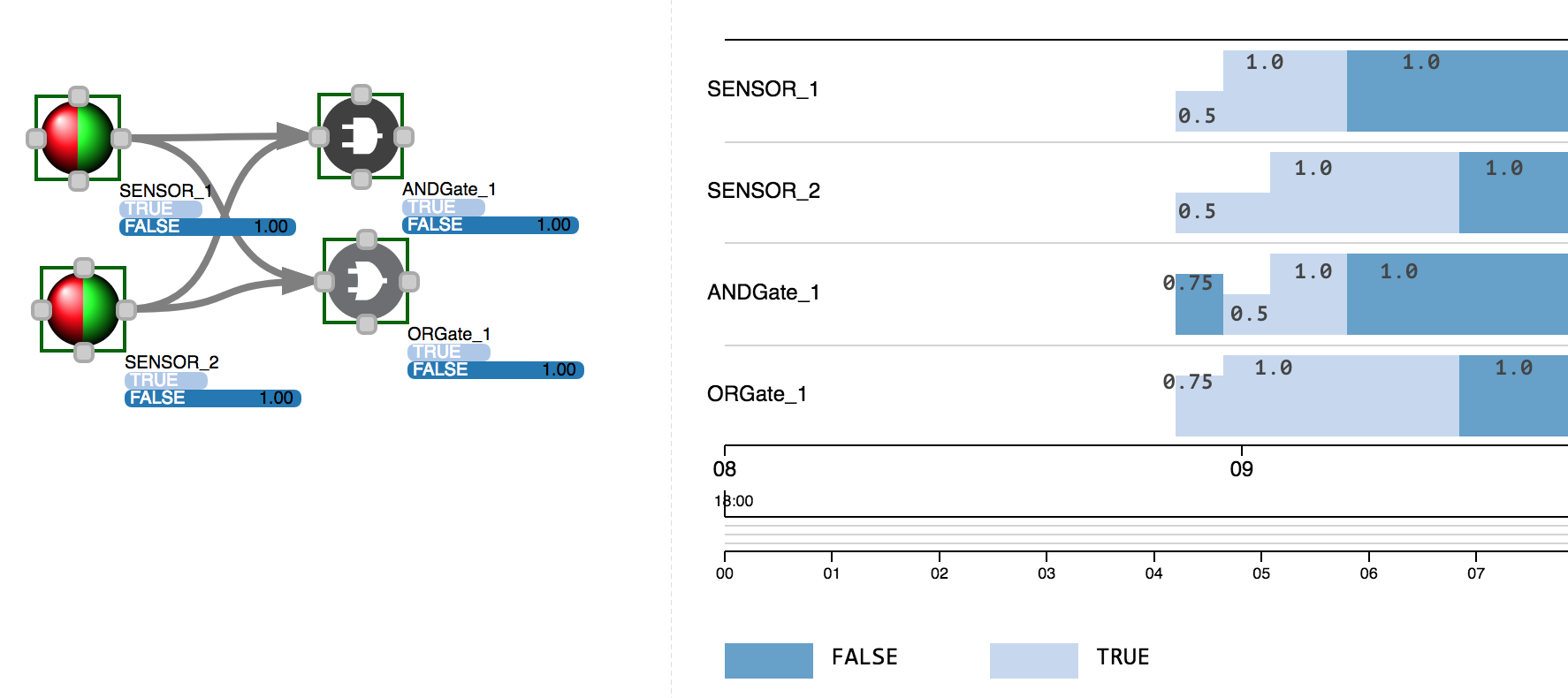
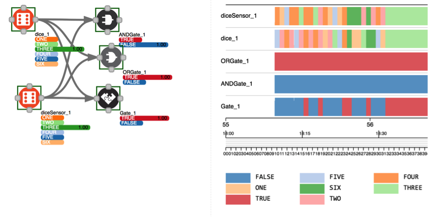
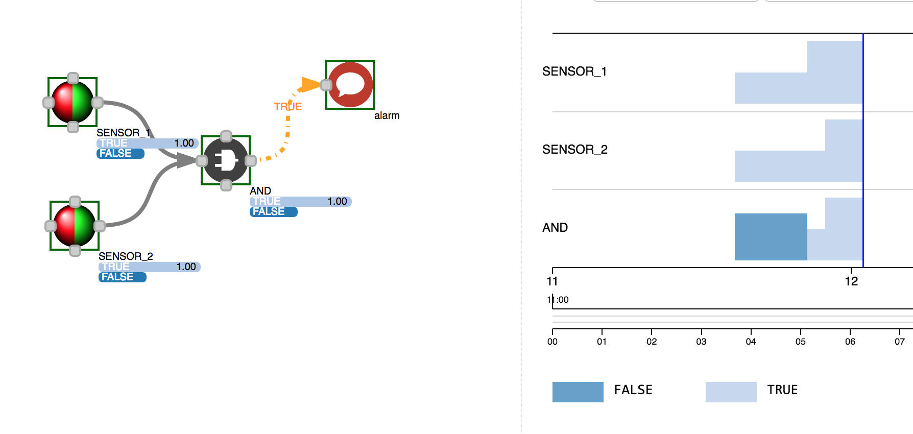
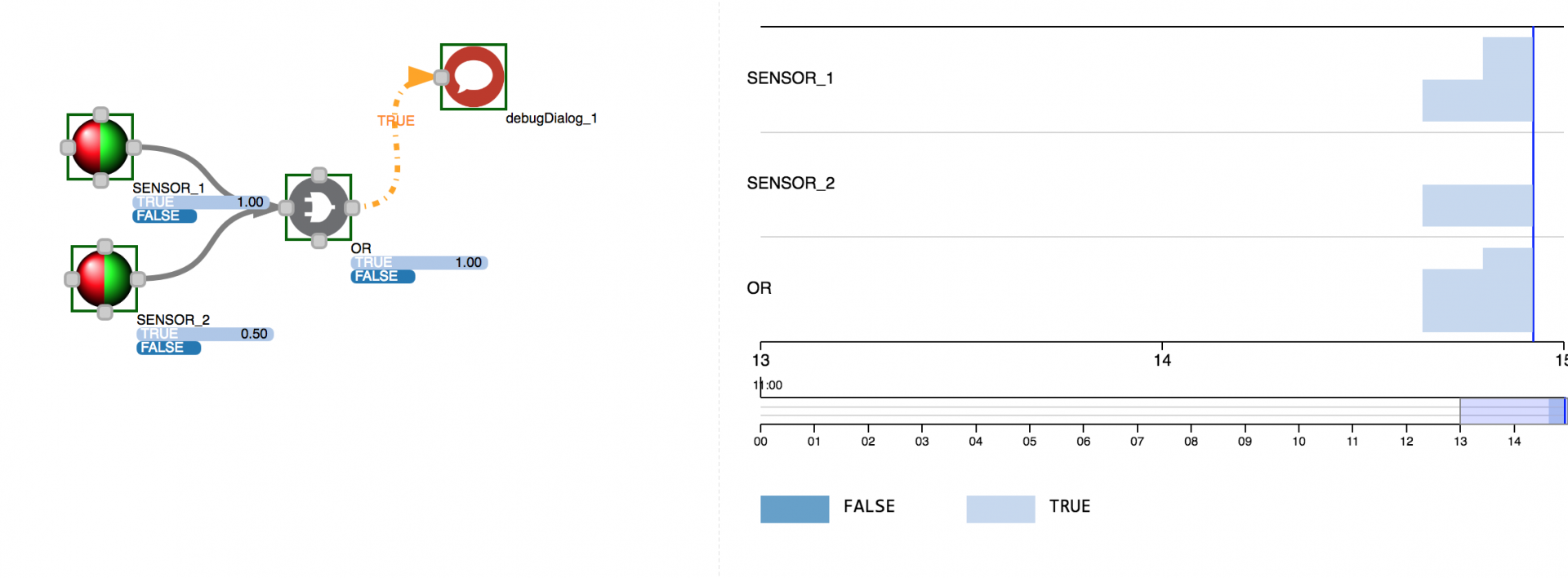
Below is the example with two sensors, with two states (TRUE, FALSE) attached to AND and OR gate, randomly changing their states over time. 0.5 means that the sensor is not yet observed (initial condition), while 1.0 means that the sensors are in one of two possible states. On the other hand, AND and OR gate values represent posterior probabilities, that are changing from 0.5, to .75 and 1.0, depending on the CPT table. For instance, in the initial condition, where both sensor states are with priors 0.5 for both TRUE and FALSE state, AND gate will be 0.75 likely in state FALSE, while OR gate with posterior probability of 0.75 in TRUE state.
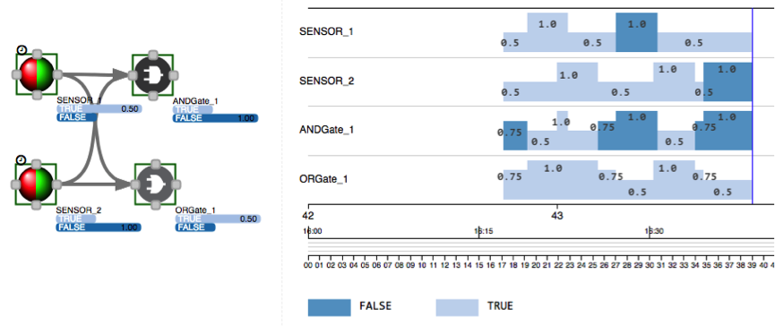
This is the same example as before, with the only difference being that now the sensors’ states are evicted after a while (using eviction flag), which means sensors switch from being fully observed (1.0) back to priors 0.5, which also changes posterior conditions for attached gates:
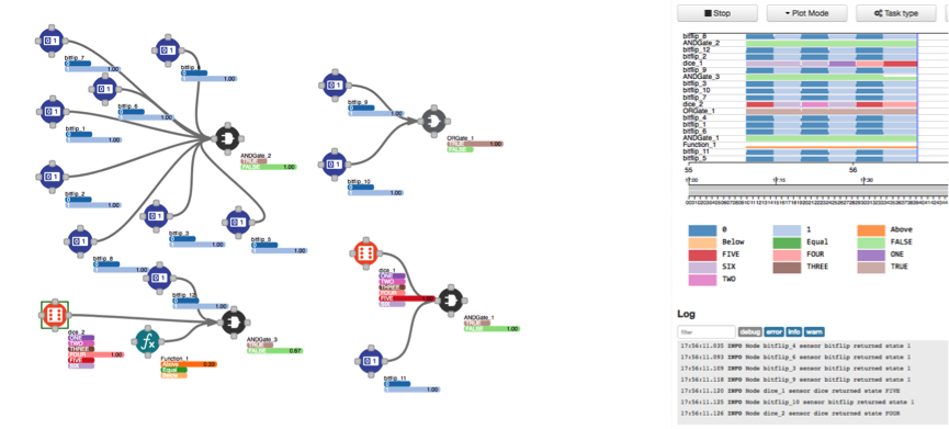
As mentioned earlier, there is also a possibility to link any set of states for any number of nodes, like in this next example, where we link 36 different outcomes, from 2 nodes with 6 states, to a desired outcome, using a general gate. Unlike using decision trees, which would require 72 nodes in the graph (662), we can achieve the same result with only 3 nodes!
In this next example we use three different gates at the same time. Please note that nothing prevents a developer from stacking gates on top of each other!
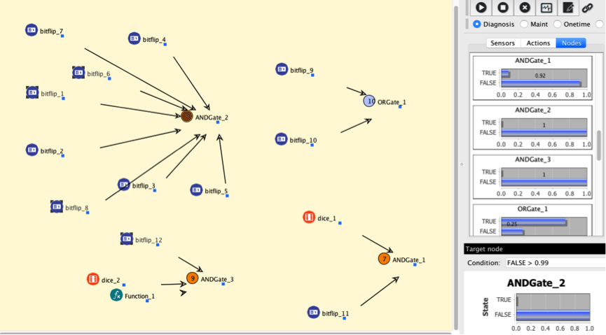
The difference between the SaaS view and the expert view for one template is this one: when we model a template in the SaaS portal, we are actually creating a Bayesian network (picture below).
In this picture, you see already some of the sensors being observed, with posteriors changing for each node as this happens:
Task control
Let’s take a closer look into one task:
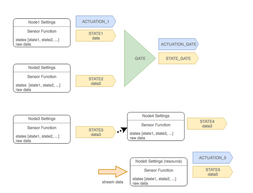
As mentioned earlier, whether a particular sensor’s function will execute depends only on the node or task settings. We can decide to run each sensor separately, with polling, or to execute the sensor based on the task clock (cron/polling/…), or by getting the sensor triggered on the outcome of another sensor, or trigger the sensor execution when stream data arrives. We can even mix these conditions together.
Task context
Once the sensor executes, both state and raw data is passed into the task context. That context is accessible to all sensors and actuators at any time. In the picture below, with the red box we show the node’s context when it becomes available in the task context, while with a yellow arrow, we represent the state for any given sensor (how long it stays in a given state depends on the eviction and the next sensor invocation).
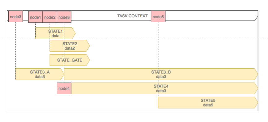
For instance, here we can see that node 5, just before execution, already had a possibility to access the context of other 4 nodes (their states and raw data). From this it is quite obvious that just by chaining sensors to each other, without any gate, we can easily implement any flow-based rule.
Inference
Once the sensor execution was successful, a few things happen: state is propagated through the network using inference algorithm; every node or gate that has attached actuators will evaluate whether the actuator needs to fire; and finally, the result of the sensor execution is stored in the task context (red boxes). The task context is always available to all sensor functions.
In the picture below, we show the node states in colour only if they are set with probability 1.
We will show two examples, where the same sensors are first attached to the AND gate, and then in the second example, where the same sensors are attached to the OR gate. Observations (labeled by red and green boxes on top) will be the same in both cases. The yellow icon just below the boxes shows when the inference happens (right after any node observation). We also assume that there is an actuator attached to the gate with condition TRUE, which is represented by a small yellow arrow on the gate graph.
In this short video, we show the example where both observations become TRUE, triggering the actuation on the AND gate:
Let’s see some other possible scenarios:
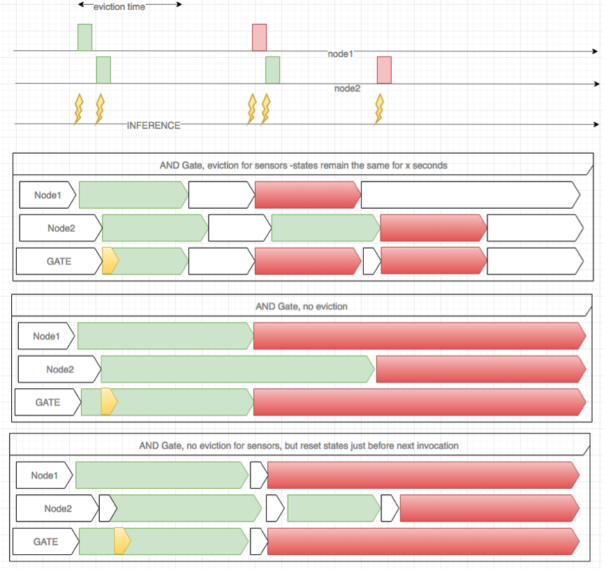
Depending on the eviction policy, the state of the sensor might remain the same till the next observation, or the node can simply reset to priors (white arrow), after the eviction time is reached.
In the first example above, node1 and node2 have the same eviction policy, which makes the gate to be fully observed only as long as both nodes are fully observed too (see section on CPT table). In the second example, states stayed observed till the next observation (sensor function) is executed.
In the third example, resetObservations flag was set true, which would make the node automatically reset to priors just before the execution of the attached sensor function.
Using the same example as above, only now with the OR gate, we can see how would the rule evolve in time.
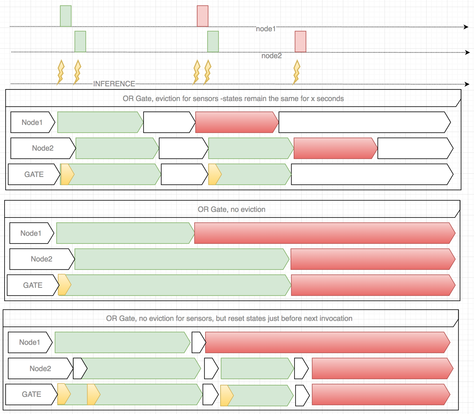
Looking at the last example, you can notice that the actuation happened twice, when the first sensor returned the TRUE state, and then when the second one returned the TRUE state, since the inference happens any time there is a new observation in the network, and in both cases, the OR gate resulted in TRUE state. Should such things be avoided, the designer can either choose to actuate on the state change (only when first time the gate becomes TRUE), or by limiting how often actuation happens, using triggering policy.
What else can be done with the Waylay engine?
Now that you know more about the Waylay inference engine programming principles, you can browse this page, where you can learn more about different integration patterns, such as:
- Raise the alarm if the stream data is above the threshold for the predefined period of time
- Counting the number of alarms within a time window or number of samples
- Flow based rules
- CEP raw data processing
- Using gates as the control flow
- Simple control using gates
- Raise the alarm if there is no data within a time window
- State pattern matching – within a time window
- JSON payload transformation and enrichment
- Mixing push and pull events, with conditional sensor execution
- Mixing push and pull events, general case
- How to synchronize different data streams
- Control flow using sequence feature
- Threshold crossing with stream data
- Timings in Waylay – merging data streams and applying formula
More on Bayesian Networks and AI
- If you are interested in learning more about Bayesian Networks, this book is a classic on bayesian networks, Probabilistic Reasoning in Intelligent Systems by Judea Pearl
- Artificial Intelligence: A Modern Approach, by Peter Norvig and Stuart J. Russell is an excellent AI book, and has a nice chapter on Probabilistic reasoning and Bayesian Networks.
- There are a lot of other great resources available on a quick google search 🙂


'%3e%3cg id='Final-Copy-2_2_' transform='translate(1275.000000, 200.000000)'%3e%3cpath class='st0' d='M7.4,12.8h6.8l3.1-11.6H7.4C4.2,1.2,1.6,3.8,1.6,7S4.2,12.8,7.4,12.8z'/%3e%3c/g%3e%3c/g%3e%3c/g%3e%3cg id='final---dec.11-2020'%3e%3cg id='_x30_208-our-toggle' transform='translate(-1275.000000, -200.000000)'%3e%3cg id='Final-Copy-2' transform='translate(1275.000000, 200.000000)'%3e%3cpath class='st1' d='M22.6,0H7.4c-3.9,0-7,3.1-7,7s3.1,7,7,7h15.2c3.9,0,7-3.1,7-7S26.4,0,22.6,0z M1.6,7c0-3.2,2.6-5.8,5.8-5.8 h9.9l-3.1,11.6H7.4C4.2,12.8,1.6,10.2,1.6,7z'/%3e%3cpath id='x' class='st2' d='M24.6,4c0.2,0.2,0.2,0.6,0,0.8l0,0L22.5,7l2.2,2.2c0.2,0.2,0.2,0.6,0,0.8c-0.2,0.2-0.6,0.2-0.8,0 l0,0l-2.2-2.2L19.5,10c-0.2,0.2-0.6,0.2-0.8,0c-0.2-0.2-0.2-0.6,0-0.8l0,0L20.8,7l-2.2-2.2c-0.2-0.2-0.2-0.6,0-0.8 c0.2-0.2,0.6-0.2,0.8,0l0,0l2.2,2.2L23.8,4C24,3.8,24.4,3.8,24.6,4z'/%3e%3cpath id='y' class='st3' d='M12.7,4.1c0.2,0.2,0.3,0.6,0.1,0.8l0,0L8.6,9.8C8.5,9.9,8.4,10,8.3,10c-0.2,0.1-0.5,0.1-0.7-0.1l0,0 L5.4,7.7c-0.2-0.2-0.2-0.6,0-0.8c0.2-0.2,0.6-0.2,0.8,0l0,0L8,8.6l3.8-4.5C12,3.9,12.4,3.9,12.7,4.1z'/%3e%3c/g%3e%3c/g%3e%3c/g%3e%3c/g%3e%3c/svg%3e) Privacy Choices
Privacy Choices